Reserved for chip conveyor mod.
Chip Conveyor parts list.
SPST 12v relay:
http://www.surpluscenter.com/Electrical/Relays-Contactors-Solenoids/DC-Relays-Contactors-Solenoids/12-VDC-40-AMP-SPST-RELAY-11-3427.axd12volt 10 amp self resetting circuit breaker:
https://www.amazon.com/Vulcan-Shortstop-Circuit-Automatic-Protective/dp/B01KAF28Q8/ref=sr_1_2?ie=UTF8&qid=1486354834&sr=8-2&keywords=12+volt+10amp+circuit+breakerMomentary On/Off/On DPDT toggle switch for reverse/off/forward of chip conveyor motor:
http://www.surpluscenter.com/Electrical/Switches/Toggle-Switches/DPDT-CO-20-AMP-MOMENTARY-MAINTAINED-TOGGLE-SWITCH-11-3279.axd!2v 100rpm intermittant duty gear motor:
http://www.surpluscenter.com/Electric-Motors/DC-Gearmotors/DC-Gearmotors/100-RPM-12-VDC-GEARMOTOR-5-1649.axd#35 chain:
http://www.surpluscenter.com/Power-Transmission/Roller-Chain-Links/Roller-Chain/35-1-10-10-BOX-OF-35-ROLLER-CHAIN-1-1163-35.axd10T #35 3/8 bore sprocket:
http://www.surpluscenter.com/Power-Transmission/Sprockets/Finished-Bore-Sprockets/10T-3-8-BORE-35P-SPROCKET-1-2413-10-AA-S.axdMount the 12 volt relay in a convenient spot, connect spade #85 directly to a ground, connect spade #30 to the load terminal of the breaker, the supply terminal of the breaker gets connected directly to the 12 volt power supply at the terminal block. Terminal #86 of relay gets connected to the lug on the terminal strip that is energized only when the saw is in the cut position. Spade #87 on the relay goes to terminal #4 of the on/off/on toggle switch. Go ahead and connect terminal #2 on the toggle to one lead of the gear motor and terminal #5 to the other terminal of the gear motor.
When making the connection on the toggle I prefer eyes instead of slip on terminals, with eyes if a screw comes loose the eye cant fall off and short against something else. When making the connection to #4 another short piece of wire should be crimped in along with the wire from the relay, that short piece then should get an eye crimped on and connected to terminal #3 on the toggle. A ground wire then should be attached to terminals #1 and 6#. With the tractor engine off and power supply hooked up with the saw in the cut position the motor should run forwards with the toggle in the On position, off when the toggle is in the Off position and backwards when the toggle is held in the momentary on position. If the motor runs backwards to the directions then reverse terminals #2 and #5.
The motor I listed comes with a 7/16 shaft, the sprocket is 3/8 bore, I chucked mine in the lathe and bored it to 7/16 after I removed the set screws. The flat in the shaft isnt required and most likely will be cut off anyways. When your sure of the final position of the sprocket take a small drill bit and dimple the motor shaft thru each setscrew hole in the sprocket hub, this is more than adequate to drive it, no key way or flat spot required. On the sprocket take an angle grinder and cut a small notch between each of the teeth, this helps to keep chips from building up on the ID, kinda like how some dirt bike sprockets are cut.
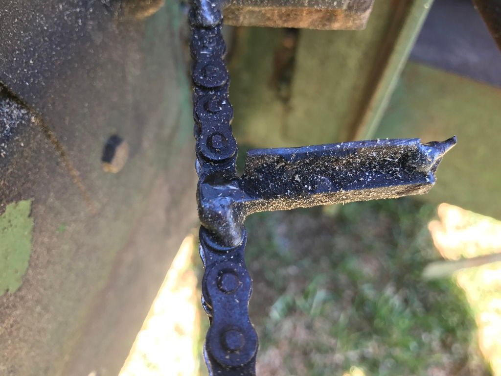
I used 3/16 key stock and welded a 2 piece to each link however far apart you desire your paddles, 2-3 seems to work fine, its easiest if you take a piece of flat stock the same height as the roller chain laying on its side, lay each piece of key stock on the flat plate of a link and weld it to the pins of the roller chain, I tried welding directly to the flat plate and ruined the first link I tried. After you determine the length you need and all the key stock is welded on then paddles can be welded to the key stock. I used 14 gauge black metal, an 1 or 1 1/2 tall is plenty, length of the paddle will be determined by your tightest spot along the chute. I also used key stock as a wear guide when it goes around the corner, grind one end at a 45 and use that like a scraper against the rollers on the chain so chips cant build up behind it. I drilled a hole thru the sheetmetal at the leading edge of that piece of keystock and chips do come thru it, so the scraper part of it is essential.
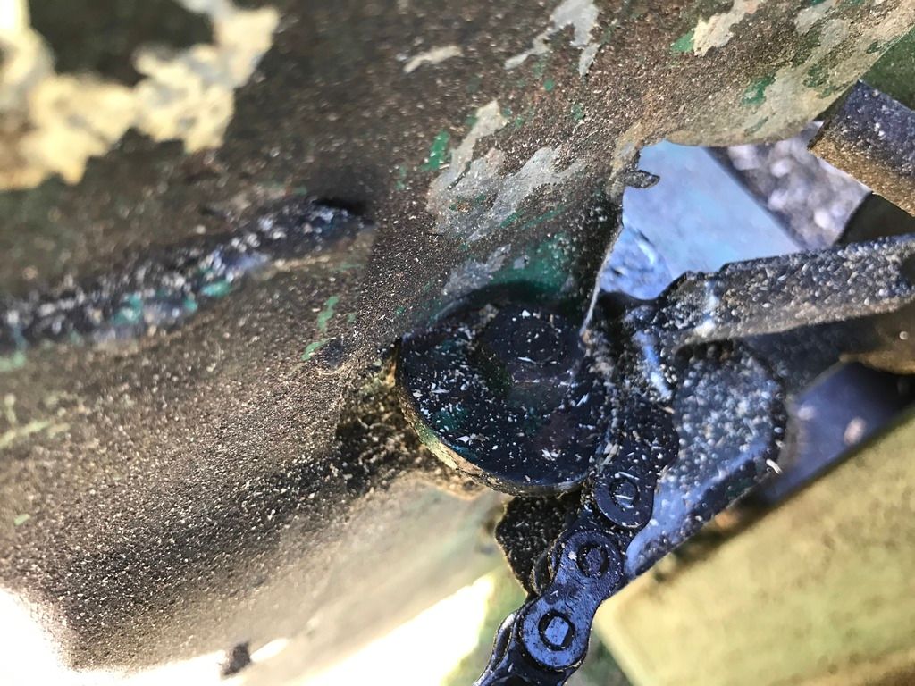
The end opposite of the motor is simply a cutout from a 1 1/2 hole saw, I believe either was 1/8 or 3/16 inch thick, I place a washer or two under it for a spacer then simply cut the head off a 1/4 bolt and welded that directly to the processor frame as a mounting stud for the idler.
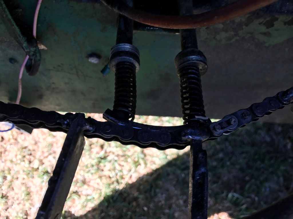
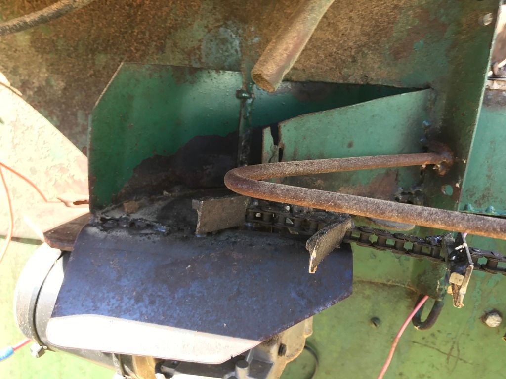
The spring loaded tensioner for the chain is two pieces of 1/4 pipe reamed out with a drill bit, then two piece of quarter inch rod welded to a piece of 3/16 keystock acts as both a tensioner and a guide, grind a slight taper on each end to help keep the chain from walking off. Tension is supplied by a spring on each rod, tension can be adjusted by simply adding or subtracting 1/4 flat washers from under the springs. Care must be taken to insure the rods and pipes are parallel on all planes or it wont work freely. I pull the hose off the bar once in awhile and oil the chain and tensioner with a little bar oil to keep everything free, I run the Stihl Blue winter oil in it year round as most of the time we dont use it much in the summer.
Closeup of paddle:
Closeup of chain tensioner:
Closeup of idler assembly, the cutout is tightened down on the stud and doesnt need to rotate:
Closeup of chute, a piece of plexiglass is cut to fit around the bar to keep the chips in the chute. The heads of #10 bolts are cut off and tacked to the top of the chute along the sides and holes drilled in the plexiglass to fit over the studs, wing nuts then are used to hold the plexiglass down.
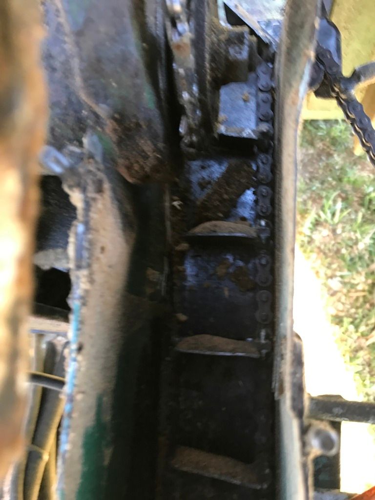
Closeup of motor assembly and guard:
 Author
Topic: Wood Eze Firewood Processor (Read 12437 times)
Author
Topic: Wood Eze Firewood Processor (Read 12437 times)